
The global demand for reliable, uninterrupted electrical power continues to expand across urban developments, commercial complexes, and industrial sites. Electrical utilities and facility engineers face constant challenges in designing distribution networks that withstand harsh environmental conditions while delivering high operational efficiency and safety. Traditional overhead power lines, while lower in initial installation costs, are vulnerable to extreme weather, wind damage, falling trees, vehicular collisions, and environmental degradation. In response to these challenges, modern electrical engineering relies heavily on subsurface power transmission networks. Central to this electrical infrastructure is the low voltage cross-linked polyethylene insulated cable, serving as a reliable Underground cable solution for power distribution systems rated up to 0.6/1kV.
The shift toward subterranean power grids requires advanced cable construction materials capable of handling mechanical stress, soil moisture, thermal variations, and potential chemical exposure. Low voltage cross-linked polyethylene power cables have emerged as the standard specification across utility power networks, industrial plants, mining operations, and commercial installations. Understanding the physical engineering, material science, operational parameters, and installation methodologies of these electrical cables provides crucial insights into how modern power networks achieve exceptional durability and energy efficiency.
Structural Design and Material Layers of Low Voltage Cables
Low voltage XLPE power cables are engineered through multi-layer construction designed to isolate electrical conductors, prevent moisture ingress, absorb mechanical impacts, and maintain structural integrity under heavy electrical loads. Every layer in the cable plays a specific functional role in guaranteeing safe continuous electrical operation beneath the ground.
Conductor Core Materials and Geometries
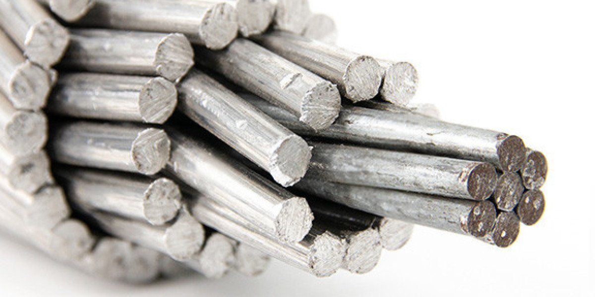
The central component of any power cable is the electrical conductor, responsible for carrying electrical current from the power source to downstream loads. Low voltage power cables utilize two primary metallic conductor materials: high-purity electrical grade copper (Cu) or electrical grade aluminum (Al).
High-purity copper conductors offer high electrical conductivity, low electrical resistance, exceptional mechanical ductility, and high tensile strength. High conductivity copper conductors minimize electrical power losses over extended distances and provide superior resistance to thermal expansion cycles during peak load operations. Flexible stranded copper conductors are frequently selected for tight installations requiring small bending radii or where high mechanical flexibility is needed.
Electrical grade aluminum conductors offer a lightweight and economical alternative to copper. Although aluminum possesses approximately 61% of the electrical conductivity of copper by cross-sectional area, its significantly lower weight and cost render it highly popular for large-scale distribution networks. Modern aluminum conductors utilize stranded circular or sector-shaped compact designs to maximize conductor fill factor and minimize overall cable outer diameter.
Conductor core configurations vary according to the electrical distribution system phase requirements. Low voltage power cables are manufactured in single-core, 2-core, 3-core, 4-core, and 5-core layouts, as well as reduced neutral setups such as 3+1 core, 3+2 core, and 4+1 core configurations. Sector-shaped conductors are often utilized in multi-core designs to create a compact, rounded cable profile, which reduces material usage and overall cable dimensions without compromising electrical cross-sectional area.
Cross-Linked Polyethylene Insulation Physics
The insulating layer directly surrounding the conductor core is constructed from cross-linked polyethylene (XLPE). Unlike conventional thermoplastic polyethylene or polyvinyl chloride (PVC), XLPE undergoes a chemical cross-linking process during manufacturing—typically via organic peroxide cross-linking or silane moisture curing. This chemical reaction transforms the linear molecular chains of polyethylene into a three-dimensional, heat-resistant thermosetting network.
The molecular structure of XLPE endows the cable with superior dielectric strength, low insulation power factor, and elevated continuous working temperature limits. Standard PVC insulated cables operate at maximum continuous conductor temperatures of 70°C, whereas XLPE insulated cables operate continuously at 90°C. Under short-circuit conditions lasting up to 5 seconds, XLPE insulation withstands thermal spikes up to 250°C without melting, deforming, or experiencing dielectric breakdown. This high thermal threshold increases the current-carrying capacity (ampacity) of the conductor, allowing smaller conductor cross-sections to convey higher power loads safely.
Bedding and Inner Sheath Protection
Directly over the insulated cores, an inner sheath or bedding layer is applied via extrusion. The inner sheath serves multiple structural roles:
It bundles multi-core insulated conductors together into a uniform circular assembly.
It cushions the insulated cores against mechanical forces exerted during the armoring process.
It provides an additional moisture barrier, preventing ambient moisture from penetrating inward toward the conductor cores.
Bedding compounds typically consist of extruded PVC or low-smoke halogen-free polymeric materials designed to adhere smoothly without damaging the underlying XLPE insulation.
Mechanical Armoring Systems
To withstand compressive forces, soil movement, stone impacts, direct burial pressure, and accidental mechanical damage during excavation, power cables intended for subterranean placement require specialized mechanical armoring. Depending on the core layout and mechanical environment, three primary armoring configurations are utilized:
Steel Wire Armor (SWA): Consisting of a full coverage layer of galvanized steel wires wrapped helically around the inner sheath, SWA provides exceptional tensile strength and heavy crush resistance. SWA is the standard armoring design for multi-core direct-burial low voltage cables installed in heavy industrial grounds, utility trenches, and unstable soil beds.
Steel Tape Armor (STA): Formed by double layers of galvanized steel tape wound spirally over the inner sheath, STA provides comprehensive mechanical shielding against flat crushing loads and mechanical impact from sharp stones or digging tools. STA armored cables offer high flexibility and physical protection in direct-burial applications where axial tensile pulling forces are moderate.
Aluminum Wire Armor (AWA): Standard ferrous armors like galvanized steel are ferromagnetic and subject to magnetic hysteresis and eddy current losses when exposed to single-core alternating current (AC) magnetic fields. Therefore, single-core AC power cables utilize non-magnetic Aluminum Wire Armor (AWA) to eliminate electromagnetic heating losses while maintaining robust physical protection.
Outer Sheath Formulations
The outermost protective layer of the power cable acts as the first line of defense against chemical attack, moisture infiltration, ultraviolet radiation, and physical abrasion. The choice of outer sheath material depends heavily on the intended installation environment:
Polyvinyl Chloride (PVC) Sheaths: Offer strong flame retardancy, excellent resistance to weather, grease, and chemicals, and high mechanical toughness at a cost-effective price point.
Low Smoke Zero Halogen (LSZH) Sheaths: Designed for enclosed public facilities, subways, tunnels, and high-occupancy commercial structures. In the event of a fire, LSZH sheathing releases minimal smoke and zero corrosive halogen gases, protecting human lives and delicate electronic control hardware.
Anti-Termite and Anti-Rodent Modifications: Specialized outer sheath additives or polyolefin outer coats can be incorporated to resist biological attacks from insects and burrowing animals in subterranean environments.
Technical Performance Metrics and Standard Specifications
Low voltage power cables must satisfy rigorous international standards to ensure safe, long-term operational performance in subsurface environments. Understanding key performance metrics enables electrical engineers and system designers to specify the exact cable construction required for specific project conditions.
Thermal Limits and Current Ratings
Operating temperature capabilities directly dictate the power delivery capacity of an Underground cable. XLPE insulation provides distinct thermal capabilities:
Continuous Operating Conductor Temperature: 90°C
Emergency Overload Conductor Temperature: Up to 130°C for temporary load spikes
Short-Circuit Conductor Temperature: 250°C (maximum duration of 5 seconds)
These thermal characteristics allow high current density operation compared to legacy insulation materials. Consequently, when replacing older PVC or paper-insulated lines, XLPE cables allow higher power throughput within the same conduit footprint or direct burial trench dimensions.
Voltage Ratings and Dielectric Integrity
Low voltage power cables are rated for operating system voltages of 0.6/1kV, where:
0.6 kV represents the rated power-frequency voltage between any phase conductor and the metallic earthing shield or earth.
1.0 kV represents the rated power-frequency voltage between any two phase conductors.
The XLPE insulation layer maintains extremely high insulation resistance, low dielectric constant, and minimal dielectric loss factor over its entire operating lifespan. These properties prevent electrical breakdown and leakage currents, even when the cable remains submerged in water-logged soils for extended periods.
Mechanical and Environmental Compliance Standards
To ensure manufacturing consistency, mechanical integrity, and electrical safety, high-grade power cables adhere to internationally recognized standard frameworks, including:
IEC 60502-1: Power cables with extruded insulation and their accessories for rated voltages from 1 kV up to 30 kV (Part 1: Cables for rated voltages of 1 kV and 3 kV).
BS 5467: Specification for armored power cables with thermosetting insulation for rated voltages of 600/1000V.
BS 6724: Specification for armored power cables having low emission of smoke and corrosive gases when affected by fire.
ASTM Standards: Applicable to copper and aluminum conductor stranding and material purity specifications.
Compliance with these manufacturing standards ensures that cables possess uniform insulation wall thickness, high tensile strength, consistent armor coverage, and low conductor electrical resistance.
Key Industry Applications of Low Voltage Power Cables
Low voltage XLPE power cables are deployed across an expansive range of commercial, industrial, municipal, and renewable energy sectors. Their robust construction allows direct placement underground, in concrete ducts, or on open cable trays.
Municipal Power Distribution and Urban Utilities
City municipalities and power distribution utilities rely extensively on subsurface cable installations to modernize urban infrastructure. Replacing overhead distribution lines with a buried Underground cable system delivers several city-wide structural improvements:
Eliminates overhead line hazards, such as fallen live wires caused by storms, ice accumulation, or vehicular collisions.
Restores clear city skylines, enhancing property values and urban aesthetics.
Reduces right-of-way spatial requirements, enabling high-density commercial and residential development.
Provides consistent power reliability to substations, street lighting networks, and municipal water pumping stations.
Heavy Industrial Plants and Petrochemical Refineries
Industrial manufacturing facilities, chemical plants, petroleum refineries, and steel mills operate continuous heavy electrical loads in demanding environments. Subsurface electrical networks supply reliable power to high-capacity motor control centers, industrial furnaces, heavy machinery, and sub-distribution panels.
In facilities processing flammable gases or chemical fluids, placing power cables subterraneanly reduces fire exposure hazards and shields power conduits from accidental mechanical strikes by overhead cranes or heavy industrial transport vehicles. Steel wire armored (SWA) and steel tape armored (STA) XLPE cables are preferred in these environments due to their physical resistance to mechanical impacts, oils, and chemical spills.
Mining and Extraction Infrastructure
Mining operations require reliable power transmission under extreme environmental conditions. Modern open-pit and subterranean mining sites utilize heavy-duty armored low voltage power cables to distribute power to excavation equipment, subterranean ventilation fans, drainage pumps, and lighting networks. Heavy steel wire armor absorbs severe impact forces from shifting rock strata and heavy haul trucks, while XLPE insulation maintains electrical integrity in high-humidity, damp underground tunnels.
Renewable Energy Plants and Grid Integration
The global transition toward clean energy has created widespread demand for subterranean power distribution networks within solar photovoltaic (PV) utility farms, onshore wind generation facilities, and battery energy storage system installations.
In solar PV power plants, low voltage power cables connect field combiner boxes and string inverters to central step-up transformer stations. Because these cables are often routed through direct burial trenches across solar arrays, XLPE insulated cables with UV-stabilized outer sheaths provide robust resistance to ground moisture and temperature fluctuations. In wind generation parks, inter-tower low voltage collection networks use armored power cables buried along access roads to convey power from individual turbine base enclosures to main collector substations.
Commercial Infrastructure, Datacenters, and High-Rise Utility Risers
Modern commercial real estate, data processing centers, shopping complexes, and hospital facilities require continuous, high-capacity electrical feeder lines. Low voltage XLPE cables serve as main power incoming feeds from utility transformers into basement main distribution switchboards. Furthermore, unarmored or aluminum-wire armored low voltage cables are installed in vertical utility shafts (risers) to distribute power across high-rise floors safely and efficiently.
In indoor commercial and datacenter installations, Low Smoke Zero Halogen (LSZH) sheathed power cables are specified to prevent toxic fume emissions in the event of an electrical fire, protecting critical computing equipment and building occupants.
Best Practices for Underground Cable Installation and Trenching
The operational life expectancy of a buried power cable system depends as much on correct installation procedures as on cable manufacturing quality. Improper handling, excessive pulling tension, sharp bend radii, or improper trench preparation can compromise cable sheathing and insulation, leading to premature electrical failure.
Site Survey, Route Planning, and Soil Analysis
Before beginning trench excavation, site engineers must perform comprehensive route planning and soil analysis. Key parameters to evaluate include:
Existing Sub-surface Utilities: Utilizing ground-penetrating radar and utility maps to avoid gas lines, water mains, fiber optic ducts, and pre-existing electrical cables.
Soil Thermal Resistivity: Soil's ability to dissipate heat generated by electrical current flowing through buried conductors directly affects cable ampacity. High thermal resistivity soils require special backfill materials to prevent thermal runaway and cable overheating.
Chemical and Water Table Conditions: Identifying acidic soils, industrial contamination, or high water tables that necessitate chemical-resistant outer sheathing or specific waterproofing barriers.
Direct Burial Trench Preparation Standards
Direct burial is an efficient method for installing low voltage armored power cables across open land or utility rights-of-way. Standard trench design guidelines follow strict engineering protocols:
Trench Depth and Width: Low voltage power cables are typically installed at minimum burial depths of 0.5 to 0.8 meters below finished ground level, depending on local electrical codes and potential surface traffic loads. Trench width must provide adequate clearance between adjacent cables to ensure proper heat dissipation and prevent mutual thermal interference.
Sand Bedding Layer: The trench bottom must be excavated cleanly and cleared of sharp rocks, debris, or roots. A bed of compacted fine sand or stone-free sieved soil at least 75 mm to 100 mm deep is placed at the bottom of the trench before laying the cable. This smooth sand bed cushions the cable outer sheath against mechanical point loads.
Cable Placement: The cable is laid smoothly into the sand bed without excessive tension or twisting. Where multiple parallel cables are laid in the same trench, specified spacing must be maintained to comply with electrical derating factors.
Thermal Backfill and Protective Cover: A second layer of sand or thermal backfill compound (100 mm deep) is placed over the laid cable. Concrete protective slabs, bricks, or heavy plastic marker tiles are then laid above the sand layer to shield the buried Underground cable from future accidental excavation damage.
Warning Marker Tape: High-visibility plastic warning tape printed with warning indicators is installed approximately 200 mm to 300 mm above the protective slabs before final backfilling and compaction of the native soil.
Conduit and Duct Installation Mechanics
In areas where direct trench excavation is impractical—such as under paved roadways, railway crossings, concrete foundations, or heavily built-in city centers—cables are pulled through pre-installed concrete banks or high-density polyethylene (HDPE) ducts.
Duct Sizing: The internal diameter of the conduit or duct should be at least 1.5 times the overall outer diameter of the cable (or bundle of cables) to minimize friction and prevent jamming during installation.
Cable Pulling Tension: Specialized cable rollers, pulling eyes, swivel links, and tension-monitoring winches are used during pulling operations. Pulling tension must never exceed maximum manufacturer-specified limits calculated based on conductor material and cross-sectional area.
Bending Radius Limitations: Bending a power cable beyond its allowable bend radius can fracture XLPE insulation, deform metallic armor, or cause sheath splitting. Armored low voltage cables generally require a minimum bending radius of 12 to 15 times the cable outer diameter during laying.
Cable Pulling Lubricants: Approved water-based pulling lubricants are applied to outer sheaths when pulling long lengths through ducts to reduce friction coefficients and lower pulling force.
Temperature Considerations During Installation
Extremely cold ambient weather affects the flexibility of polymeric outer sheaths and XLPE insulation. If cable installation occurs at temperatures below 0°C, the protective outer sheath can become brittle and crack when unreeled or bent. Electrical codes mandate that cables be stored in a heated environment or pre-heated using temporary thermal enclosures before laying when ambient temperatures fall below freezing.
Splicing, Termination, and Earthing Engineering
Proper jointing and termination of low voltage power cables are critical to maintaining continuous electrical performance, mechanical armor integrity, and moisture resistance across the entire distribution circuit.
Heat-Shrink and Cold-Shrink Jointing Systems
When long cable runs exceed standard drum delivery lengths, or when repairing damaged sections, straight-through cable joints are installed. Modern low voltage cable jointing utilizes heat-shrink or cold-shrink polymeric sleeve technologies:
Conductor Connections: Conductive cores are joined using mechanical shear-bolt connectors or compression crimp sleeves, ensuring low electrical contact resistance and high mechanical pull-out strength.
Insulation Restoration: Thick-walled cross-linked polyolefin heat-shrink tubing lined with hot-melt adhesive is applied over the connected conductors to restore dielectric insulation strength equal to or exceeding original factory standards.
Outer Protection and Waterproofing: An outer heavy-duty protective sleeve seals the entire joint against moisture penetration, chemical ingress, and mechanical impact.
Armoring Earthing and Cable Gland Termination
At switchboard entries, transformer boxes, and motor terminal enclosures, power cables terminate using brass mechanical cable glands.
Mechanical Retention and Sealing: Industrial cable glands grip both the outer sheath and the inner bedding layer while providing an environmental seal rated up to IP66/IP68 against water and dust entry.
Armor Earthing Bonding: The metallic armor layer (SWA, STA, or AWA) must be securely clamped inside the cable gland earth ring or earthing tag. Proper earthing of the metallic armor ensures that fault currents pass safely to ground in the event of an internal insulation breakdown, tripping protective circuit breakers immediately and protecting site personnel from hazardous touch voltages.
Maintenance, Diagnostic Testing, and Quality Control
Ensuring long-term operational integrity requires rigorous quality assurance during cable manufacturing, pre-commissioning testing following installation, and routine diagnostic maintenance throughout the operational life cycle of the power network.
Pre-Commissioning Electrical Testing Protocols
Before energizing a newly installed buried cable system, electrical engineers conduct a battery of standard pre-commissioning tests to verify insulation integrity and proper phase connection:
Insulation Resistance Testing: Utilizes a high-voltage megohmmeter to measure insulation resistance between phase conductors, between conductors and neutral, and between conductors and metallic armor/earth. High insulation resistance values confirm that no moisture penetration or installation damage has occurred.
Conductor Resistance Testing: Verifies phase conductor continuity and ensures electrical resistance values match factory design specifications, confirming that mechanical joints or connectors are properly tightened.
High Voltage Withstand Testing: Applies an elevated direct current (DC) or alternating current (AC) test voltage for a specified duration to verify dielectric stamina under voltage stress.
Armor Continuity Testing: Checks electrical resistance across metallic armor pathways and earth connections to ensure effective grounding protection.
Fault Detection Methodologies
While well-installed XLPE power cables operate reliably for decades, external excavation damage, ground shifting, or severe electrical overloads can occasionally induce localized cable faults. Modern diagnostic tools enable technicians to pinpoint fault locations accurately without excavating entire cable runs:
Time Domain Reflectometry: Sends low-voltage high-frequency pulses along the cable. Impedance discontinuities—such as open-circuit breaks or short-circuit insulation breakdown—reflect signals back to the instrument. Calculating reflection time delays determines the exact distance to the fault location.
Acoustic Pinpointing and Surge Generators: High-energy surge generators send high-voltage pulses down the damaged cable, causing an electrical arc at the fault site. Ground microphones detect the acoustic sound wave emitted beneath the ground, pinpointing the excavation site to within centimeters.
Quality Assurance and Manufacturing Standards
Leading global power cable manufacturers implement strict quality management systems across every stage of production. From high-purity electrolytic copper rod drawing and high-speed multi-wire stranding to triple-extrusion continuous vulcanization lines, precision manufacturing ensures uniform insulation thickness, concentric conductor positioning, and void-free XLPE insulation structure.
In-line spark testing, dimensional laser monitoring, thermal aging tests, tensile strength evaluations, and flame retardancy checks ensure that finished cable products fully conform to international power distribution standards before shipment.
Final Thoughts
Low voltage XLPE power cables represent a core technological pillar of modern subsurface power distribution networks. By replacing vulnerable overhead lines with robust, armored underground electrical conduits, utilities, industrial facilities, and commercial enterprises achieve superior power stability, operational safety, and aesthetic integration. The technical synergy of high-purity electrical conductors, thermal-resistant cross-linked polyethylene insulation, protective metallic armoring, and specialized outer sheathing enables these cable systems to deliver consistent electrical performance even in harsh soil conditions, wet environments, and heavy-duty industrial installations.
Adhering to proper engineering guidelines during route selection, direct burial trench preparation, cable pulling, joint termination, and pre-commissioning testing guarantees optimal service life spanning decades. As global urbanization accelerates and renewable energy projects expand across diverse landscapes, high-integrity subsurface power cables remain vital to building safe, resilient, and high-efficiency energy infrastructure around the world.